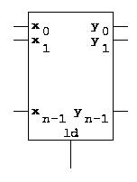
When the ld input is 0, the outputs are uneffected by any clock transition. When the ld input is 1, the x inputs are stored in the register at the next clock transition, making the y outputs into copies of the x inputs before the clock transition.
We can explain this behavior more formally with a state table. As an example, let us take a register with n = 4. The left side of the state table contains 9 columns, labeled x0, x1, x2, x3, ld, y0, y1, y2, and y3. This means that the state table has 512 rows. We will therefore abbreviate it. Here it is:
  ld x3 x2 x1 x0 y3 y2 y1 y0 | y3' y2' y1' y0'
  -------------------------------------------
   0 -- -- -- -- c3 c2 c1 c0 | c3  c2  c1  c0
   1 c3 c2 c1 c0 -- -- -- -- | c3  c2  c1  c0
As you can see, when ld is 0 (the top half of the table), the right side of the table is a copy of the values of the old outputs, independently of the inputs. When ld is 1, the right side of the table is instead a copy of the values of the inputs, independently of the old values of the outputs.
Registers play an important role in computers. Some of them are visible to the programmer, and are used to hold variable values for later use. Some of them are hidden to the programmer, and are used to hold values that are internal to the central processing unit, but nevertheless important.
We use this symbol for registers (notice that we have omitted the clock signal, as it is understood):
