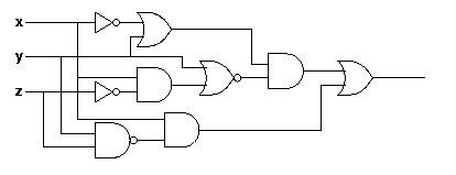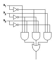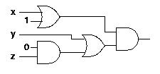
Examples:


You can trivially convert the truth table for an arbitrary circuit into an expression. The expression will be in the form of a sum of products of variables and there inverses. Each row with output value of 1 of the truth table corresponds to one term in the sum. In such a term, a variable having a 1 in the truth table will be uninverted, and a variable having a 0 in the truth table will be inverted.
Take the following truth table for example:
  x y z | f
  ---------
  0 0 0 | 0
  0 0 1 | 0
  0 1 0 | 1
  0 1 1 | 0
  1 0 0 | 1
  1 0 1 | 0
  1 1 0 | 0
  1 1 1 | 1
The corresponding expression is:

Since you can describe any combinatorial circuit with a truth table, and you can describe any truth table with an expression, you can describe any combinatorial circuit with an expression.

The left one requires two gates, one and-gate and one or-gate. The second expression requires two and-gates and one or-gate. It seems obvious that the first one is preferable to the second one. However, this is not always the case. It is not always true that the number of gates is the only way, nor even the best way, to determine simplicity.
We have, for instance, assumed that gates are ideal. In reality, the signal takes some time to propagate through a gate. We call this time the gate delay. We might be interested in circuits that minimize the total gate delay, in other words, circuits that make the signal traverse the fewest possible gates from input to output. Such circuits are not necessarily the same ones that require the smallest number of gates.